|
|
Machine Tool Shanks & Tapers
|
Kwik-Switch Taper (Universal Engineering)
|
Kwik-Switch was developed by Universal Engineering.
Collis makes fully compatible tooling they call Rapid-Switch. SPI and Smith Tool also make compatible tooling.
|
|
 
Size |
A |
B |
C |
E |
F |
H |
J |
K |
L |
M |
100 |
0.875 |
1.44 |
0.16 |
0.312 |
0.250 |
1.12 |
1.56 |
0.375 |
1.06 |
0.68 |
200 |
1.312 |
2.50 |
0.22 |
0.375 |
0.312 |
1.75 |
2.12 |
0.500 |
1.68 |
0.97 |
300 |
1.625 |
2.94 |
0.28 |
0.438 |
0.375 |
2.00 |
2.50 |
0.500 |
1.94 |
1.22 |
400 |
2.250 |
3.62 |
0.34 |
0.500 |
0.438 |
2.81 |
3.25 |
0.625 |
2.75 |
1.7 |

| |
  Kwik-Switch Tooling for sale:
|
[Back to Top of page]
SPI Quick Change shank
|
 This Tool Shank looks very similar to Universal Kwik-Switch. However it is totally incompatible with Kwik-Switch. This Tool Shank looks very similar to Universal Kwik-Switch. However it is totally incompatible with Kwik-Switch.
I don't know who developed it or if there is an industry standard.
See SPI Catalog pages for tooling with this shank.
Nikken and Yuasa also make (made ?) compatible tooling.
Independent of who made the unit, on this site I refer to all shanks and masters compatible with the
 "SPI Quick Change 75-3xx shank" as "SPI Quick Change 3" or "SPIQC-3". "SPI Quick Change 75-3xx shank" as "SPI Quick Change 3" or "SPIQC-3".
Likewise with sizes 4 and 5 (SPIQC-4 and SPIQC-5).
|
|
 
Measured values from actual units (mostly provided by Brian and Tom of Scorpion Technologies Ltd.)
Size |
SPI # |
Nikken # |
Yuasa # |
D1 |
D2 |
D3 max* |
L1 |
L2 |
L3 |
L4 |
L5 |
3 |
75-3xx |
xx30-xx |
? |
0.70 |
1.24 |
1.34 |
1.88 |
2.17 |
0.19 |
0.35 |
1.57 |
4 |
75-4xx |
xx40-xx |
? |
0.85 |
1.50 |
1.65 |
2.24 |
2.54 |
0.22 |
0.45 |
1.97 |
5 |
75-5xx |
xx50-xx |
? |
1.28 |
2.25 |
2.6 |
3.38 |
3.81 |
0.37 |
0.615 |
2.81 |
* I don't know what the actual D3 max value is. The values given are the max of several measured values and
should be close to the actual max value.
[Back to Top of page]
CAT, CV or V-flange Taper
|
aka: ANSI B5.50, Caterpillar "V-Flange" standard, ISO 7388-1, IS 11173 (TC), DIN 69871, NFE 62540.
Units built to the international standards (DIN, ISO & NFE) are commonly considered interchangeable with
ANSI (Caterpillar) shanks. However, there are a few differences.
|
|
 
ANSI B5.50 (from Kennametal catalog 7060)
Size |
D1 |
D2 |
D3 |
L |
F1 |
F2 min |
A |
G |
30 |
1.250
(31.75) |
1.812
(46.02) |
1.250
(31.75) |
1.875
(47.63) |
0.750
(19.05) |
1.375
(35.00) |
0.125
(3.18) |
1/2-13
thread |
40 |
1.750
(44.45) |
2.500
(63.05) |
1.750
(44.45) |
2.687
(68.25) |
0.750
(19.05) |
1.375
(35.00) |
0.125
(3.18) |
5/8-11
thread |
45 |
2.250
(57.15) |
3.250
(82.50) |
2.250
(57.15) |
3.250
(82.55) |
0.750
(19.05) |
1.375
(35.00) |
0.125
(3.18) |
3/4-10
thread |
50 |
2.750
(69.85) |
3.875
(98.41) |
2.750
(69.85) |
4.000
(101.60) |
0.750
(19.05) |
1.375
(35.00) |
0.125
(3.18) |
1-8
thread |
60 |
4.250
(107.95) |
5.500
(139.70) |
4.250
(107.95) |
6.375
(161.93) |
0.750
(19.05) |
1.500
(38.10) |
0.125
(3.18) |
1 1/4-7
thread |
ISO 7388-1, DIN 69871, NFE 62540
Size |
D1 |
D2 |
D3 max |
L |
F1 |
F2 min |
A |
G |
30 |
31.75 |
50 |
45 |
47.8 |
15.9 |
35 |
3.2 |
M12 |
40 |
44.45 |
63.55 |
50 |
68.4 |
15.9 |
35 |
3.2 |
M16 |
45 |
57.15 |
82.55 |
63 |
82.7 |
15.9 |
35 |
3.2 |
M20 |
50 |
69.85 |
97.5 |
80 |
101.75 |
15.9 |
35 |
3.2 |
M24 |
[Back to Top of page]
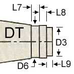
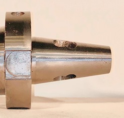
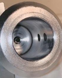
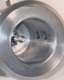
NMTB (Quick Change) Shank
|
ANSI B5.18, National Machine Tool Builders' Association, 1927. DIN 2080 / IS 2340, ISO R 290-2583
Also called Quick Change, NMTB, MM, National Standard, American Standard Machine Taper, etc.
Units built to the ISO standards are commonly considered interchangeable with ANSI units. However,
there are a few differences. (See Tables below). Most (but not all) NMTB shanks are compatible with
the corresponding size Erickson Quick-Change Spindles. (See discussion below the tables).
|
|
 
ANSI B5.18 (from Kennametal catalog 7060)
Size |
D1 |
D2 |
D3 |
D4 max |
D5* |
L1 |
L2 |
L3 |
L4 |
L5 |
L6 |
G |
30 |
1.250
[31.75] |
0.655
[16.24] |
0.673
[17.09] |
1.380
[35.05] |
1.812
[46.02] |
2.690
[68.33] |
0.810
[20.57] |
0.125
[3.18] |
0.076
[1.93] |
0.344
[8.74] |
0.359
[9.12] |
1/2-13
thread |
40 |
1.750
[44.45] |
0.935
[23.75] |
0.984
[25.00] |
1.890
[48.0] |
2.500
[63.5] |
3.690
[93.73] |
1.180
[29.97] |
0.188
[4.78] |
0.076
[1.93] |
0.313
[7.95] |
? |
5/8-11
thread |
50 |
2.750
[69.85] |
1.495
[37.97] |
1.545
[39.24] |
2.760
[68.6] |
3.500
[88.9] |
5.000
[127.0] |
1.000
[25.4] |
0.188
[4.78] |
0.141
[3.58] |
0.453
[11.51] |
? |
1-8
thread |
* These are Kennametal dimensions. D5 varies with different mfgs. My Erickson Quick-Change 30 master
can accept up to 1.86" dia flange. Some import NMTB-30 tooling I've seen is as large as 1.96".
ISO R 297-2583 and DIN 2080
Size |
D1 |
~ |
D3 |
D4 max |
D5 |
L1 |
L2 |
~ |
L4 |
L5 |
L6 min |
G |
30 |
31.75 |
~ |
? |
? |
50 |
68.39 |
? |
~ |
1.62 |
8 |
? |
M12 |
DO40 |
44.45 |
~ |
22.63 |
50 |
63 |
93.40 |
? |
~ |
1.6 |
10 |
11.0 |
M16 |
45 |
57.15 |
~ |
? |
? |
80 |
106.8 |
? |
~ |
3.2 |
12 |
? |
M20 |
DT50 |
69.85 |
~ |
34.25 |
78 |
97.5 |
126.8 |
25 |
~ |
3.2 |
12 |
16.0 |
M24 |
Size |
D6 |
D7 |
L7 |
L8 |
L9 |
DO40 |
24.0 |
21.05 |
7.0 |
4.4 |
7.0 |
DT50 |
38.00 |
~ |
7.0 |
10 |
7.0 |
|
|
|
NMTB shank compatibility with Erickson Quick-Change Spindles:
The NMTB shank was developed for use in the NMTB spindle which uses a draw bar to pull the shank up into the spindle. Tool flange thickness, distance from the gage line of the taper to the outward face of the flange and the flange diameter are not critical dimensions when used in the NMTB spindle. As a result, these dimensions were not consistent between all manufacturers of NMTB tooling.
The Erickson Tool Company developed the Erickson Quick-Change spindle to use the NMTB 30, 40, 45 and 50 tool holders already in existence. The Erickson QC system does not use a draw bar, it uses a quarter turn "locknut" to push and hold the tool taper in the spindle. Two "lips" in the nut push against the outer face of the tool flange. The key dimension (gage distance) that causes some NMTB holders to not work in an Erickson Quick-Change spindle is the distance between the taper gage line and the outer face of the flange (gage distance = L4 + L5 in above tables). Gage distance on some NMTB holders is too large, which does not allow the "lips" in the QC nut to engage the outside face of the flange.
The other issue is that the flange diameter (D5) on some NMTB holders (mostly cheaper imports) is too large to fit in the mouth of the Erickson Quick-Change spindle nut.
All NMTB holders made by Erickson work fine (they are marked Quick-Change), all Universal Engineering holders work fine and I've read that Kennametal, Collis and Valenite holders work fine (at least the ones made in the last 20 years or so). The compatibility of other holders is in question. However, all is not lost, the flange of the tools that do not work can be ground down a small amount and then they work fine in an Erickson spindle without affecting operation in an NMTB spindle.
(See Erickson grinding procedure)
The "tail" of the NMTB shank is not required when mounting in an Erickson Quick-Change Spindle. So 30-Taper and 40-Taper tooling, without tail, work fine as long as the flange dimensions are correct. DO40 and DT50 tooling can also be used in Erickson Quick-Change spindles, but you may need to take a bit off the tail "ribs" on some tooling for clearance in the Erickson QC spindle.
|
|
|
Erickson QC Tooling for sale:
|
|
QC 30
QC 40
QC 50
|
Note: These links only show items I have confirmed are compatible with Erickson Quick-Change Spindles.
Other items I have for sale may well be compatible but I have not verified that they are compatible.
|
[Back to Top of page]
BD (Boston Digital) Shank
|
Also known as: Boston Digital and xx-Taper (e.g. 30-Taper or 40-Taper, etc.)
For 30+ years I knew this taper as xx-Taper, But recently I found it is a "Boston Digtal" Shank
All examples I have encountered are fully compatible with Erickson Quick Change Spindles.
|
|
 
Most of these measurments I got from units I have
Size |
D1 |
D5 |
L1 |
L3 |
L4 |
L5 |
G |
BD30 |
? |
? |
? |
? |
? |
? |
? |
BD40 |
1.750 |
2.5 |
2.575 |
0.625 |
0.079 |
0.31 |
5/8-11 thread |
BD50 |
? |
? |
? |
? |
? |
? |
? |
[Back to Top of page]
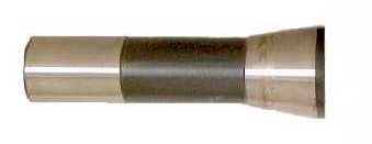
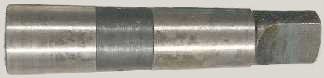
FL Quick Change Taper shank
|
I don't know if there is an industry standard. I assume it is proprietary to FL Tool Holders
The "tail" has 2 flats for positive drive.
See FL Tool Holders Catalog for tooling with this shank.
|
|
 
Values are from FL Tool Holders catalog (except where noted)
Series |
D1 |
D2 * |
L * |
T |
A° * |
1002 |
0.6875" |
? |
? |
7/8-12 |
?° |
2002 |
1.000" |
? |
? |
1.25-12 |
?° |
3002 |
1.250" |
? |
? |
1.5-12 |
?° |
4002 |
1.750" |
? |
? |
2-12 |
?° |
5002 |
2.250" |
1.45" |
4" |
2.5-12 |
17° |
6002 |
2.750" |
? |
? |
3-12 |
?° |
* These are my caliper measurements from units I have.
[Back to Top of page]
BT Taper
|
Also known as: JMTBA AS-403 "BT", JIS B 6339 - 1986, JIS B6339 - 1992, ISO 7388/1 - 1983
|
|
 
Size |
D1 |
D2 |
D3 |
L |
F |
A |
G |
BT30 |
1.250
(31.75) |
1.811
(46.00) |
( ) |
1.906
(48.40) |
0.866
(22.00) |
0.079
(2.00) |
M12
thread |
BT35 |
1.500
(38.10) |
2.087
(53.00) |
( ) |
2.224
(56.50) |
0.945
(24.00) |
0.079
(2.00) |
M12
thread |
BT40 |
1.750
(44.45) |
2.480
(63.00) |
( ) |
2.575
(65.40) |
1.063
(27.00) |
0.079
(2.00) |
M16
thread |
BT45 |
2.250
(57.15) |
3.346
(85.00) |
1.700
(43.2) |
3.260
(82.80) |
1.299
(33.00) |
0.118
(3.00) |
M20
thread |
BT50 |
2.750
(69.85) |
3.937
(100.00) |
2.787
(70.8) |
4.008
(101.80) |
1.496
(38.00) |
0.118
(3.00) |
M24
thread |
[Back to Top of page]
Unknown 30 Shank
|
I call these UNK30 or 30-Taper3 shank because I don't know what else to call them.
I got a mess of these many years ago from Boeing Surplus.
All the units I have are balanced for high speed operation..
The shank taper is 7/24 (same as BT, CAT, NMTB, BD, etc)
The drive lug slots in the flange are the same shape and width as BT30 and same width as CAT30 (approx. 5/8")
The draw-bar / pull-stud thread is 1/2-20 (vs. CAT30 1/2-16 or BT30 M12),
These are NOT compatible with Erickson Quick-Change 30 Spindle.
|
|
I got these measurments from units I have
Size |
D1 |
D2 |
L |
F |
A |
G |
30 |
1.250 |
2.5 |
1.906 |
0.69 |
0.079 |
1/2-20 thread |
|
All units have a 1/4-20 tapped hole, in the base of the bore, through to the hollow shank.
|

|
Some had a Treaded Stud mounted in the threaded bottom hole.
|
|
I made tool and removed all the studs.
25 studs and tool available. Contact me

|
|
[Back to Top of page]
R8 Shank
|
Also referred to as M1TR taper. This shank is held in place by a drawbar.
|
|
[Back to Top of page]
Morse Taper Shank
|
Generally referred to as MTx (ie MT3 for a #3 Morse Taper).
The taper range is from #0 to #7, and while all have different tapers, they are approximately 5/8" per foot.
With a tang it is the same as DIN 228 Form B.
|
|


MT
Size |
D1(1)
Gage Dia. |
D2(2) |
L2(3) |
Taper
per ft. |
L1 |
L3 |
H |
Stub
L1(4) |
Stub
L3 |
Stub
H |
0 |
0.3561 |
0.252 |
2 |
0.62460 |
2-11/32 |
1/4 |
0.1562 |
~ |
~ |
~ |
1 |
0.475 |
0.369 |
2-1/8 |
0.59858 |
2-9/16 |
3/8 |
0.2031 |
1-5/16 |
5/16 |
13/64 |
2 |
0.700 |
0.572 |
2-9/16 |
0.59941 |
3-1/8 |
7/16 |
0.2500 |
1-11/16 |
7/16 |
19/64 |
3 |
0.938 |
0.778 |
3-3/16 |
0.60235 |
3-7/8 |
9/16 |
0.3125 |
2 |
9/16 |
25/64 |
4 |
1.231 |
1.020 |
4-1/16 |
0.62326 |
4-7/8 |
5/8 |
0.4787 |
2-3/8 |
11/16 |
33/64 |
4.5 |
1.500 |
1.266 |
4-1/2 |
0.62400 |
? |
? |
? |
~ |
~ |
~ |
5 |
1.748 |
1.475 |
5-3/16 |
0.63151 |
6-1/8 |
3/4 |
0.6250 |
3 |
15/16 |
3/4 |
6 |
2.494 |
2.116 |
7-1/4 |
0.62565 |
8-9/16 |
1-1/8 |
0.7500 |
~ |
~ |
~ |
7 |
3.270 |
2.750 |
10 |
0.62400 |
11-5/8 |
1-3/8 |
1.1250 |
~ |
~ |
~ |
|
(1) |
D1 (gage line dia. of shank) is the diameter of the mouth of the MT socket. |
|
(2) |
D2 is the diameter of the bottom of the socket at depth L2 from the mouth (D1). |
|
(3) |
L2 is the length (depth) of the Socket Taper. |
|
(4)
|
D1 and Taper of Stub (short) MT shank is same as standard length MT shank.
(Stub shanks fit in standard length sockets, but the tang will not be engaged in the tang slot of the socket) |
[Back to Top of page]
Jacobs Taper
|
Generally referred to as JTx (ie JT3 for a #3 Jacobs Taper).
|
|
Size |
Large
End |
Small
End Dia. |
Taper
Length |
Taper
per ft. |
JT0 |
0.2500" |
0.2284" |
0.44" |
0.5915 |
JT1 |
0.3840" |
0.3334" |
0.66" |
0.9751 |
JT2 short |
0.5488" |
0.4876" |
0.75" |
0.9786 |
JT2 |
0.5590" |
0.4876" |
0.88" |
0.9786 |
JT33 |
0.6240" |
0.5605" |
1.00" |
0.7619 |
JT6 |
0.6760" |
0.6241" |
1.00" |
0.6229 |
JT3 |
0.8110" |
0.7461" |
1.22" |
0.6390 |
JT4 |
1.1240" |
1.0372" |
1.66" |
0.6289 |
JT5 |
1.4130" |
1.3161" |
1.88" |
0.6201 |
|
|
[Back to Top of page]
B-Taper (DIN ISO 239)
Size |
Large
End |
Small
End Dia. |
Taper
Length |
Taper
per ft.** |
B6 |
6,350mm
0.2500" |
5,85mm
0.2303" |
10mm
0.3937" |
0.6 |
B10 |
10.094mm
0.3974" |
9,4mm
0.3701" |
14,5mm
0.5709" |
0.5743 |
B12 |
12,065mm
0.4750" |
11,1mm
0.4370" |
18,5mm
0.7283" |
0.6259 |
B16 |
15,733mm
0.6194" |
14,5mm
0.5709" |
24mm
0.9449" |
0.6165 |
B18 |
17,780mm
0.7000" |
16,2mm
0.6378" |
32mm
1.2598" |
0.5925 |
B18* |
17,431mm
0.6863" |
16,2mm
0.6378" |
25mm
0.9843" |
0.5909 |
B22 |
21,793mm
0.8580" |
19,8mm
0.7795" |
40,5mm
1.5946" |
0.5905 |
B24 |
23,825mm
0.9380" |
21,3mm
0.8386" |
50,5mm
1.9882" |
0.6 |
* 7mm short of DIN ISO 239
** 12((D-d)/L)
|
|
[Back to Top of page]
Jarno Taper
Size |
Large
End |
Small
End Dia. |
Taper
Length |
Taper
per ft. |
#2 |
0.2500" |
0.2000" |
1.00" |
0.6000 |
#3 |
0.3750" |
0.3000" |
1.50" |
0.6000 |
#4 |
0.5000" |
0.4000" |
2.00" |
0.6000 |
#5 |
0.6250" |
0.5000" |
2.50" |
0.6000 |
#6 |
0.7500" |
0.6000" |
3.00" |
0.6000 |
#7 |
0.8750" |
0.7000" |
3.50" |
0.6000 |
#8 |
1.0000" |
0.8000" |
4.00" |
0.6000 |
#9 |
1.1250" |
0.9000" |
4.50" |
0.6000 |
#10 |
1.2500" |
1.0000" |
5.00" |
0.6000 |
#11 |
1.3750" |
1.1000" |
5.50" |
0.6000 |
#12 |
1.5000" |
1.2000" |
6.00" |
0.6000 |
#13 |
1.6250" |
1.3000" |
6.50" |
0.6000 |
#14 |
1.7500" |
1.4000" |
7.00" |
0.6000 |
#15 |
1.8750" |
1.5000" |
7.50" |
0.6000 |
#16 |
2.0000" |
1.6000" |
8.00" |
0.6000 |
#17 |
2.1250" |
1.7000" |
8.50" |
0.6000 |
#18 |
2.2500" |
1.8000" |
9.00" |
0.6000 |
#19 |
2.3750" |
1.9000" |
9.50" |
0.6000 |
#20 |
2.5000" |
2.0000" |
10.00" |
0.6000 |
|
|
[Back to Top of page]
Brown & Sharpe Taper
Size |
Large
End |
Small
End Dia. |
Taper
Length |
Taper
per ft. |
#1 |
0.2392" |
0.2000" |
0.94" |
0.5020 |
#2 |
0.2997" |
0.2500" |
1.19" |
0.5020 |
#3 |
0.3753" |
0.3125" |
1.50" |
0.5020 |
#4 |
0.4207" |
0.3500" |
1.69" |
0.5024 |
#5 |
0.5388" |
0.4500" |
2.13" |
0.5016 |
#6 |
0.5996" |
0.5000" |
2.38" |
0.5033 |
#7 |
0.7201" |
0.6000" |
2.88" |
0.5010 |
#8 |
0.8987" |
0.7500" |
3.56" |
0.5010 |
#9 |
1.0775" |
0.9001" |
4.25" |
0.5009 |
#10 |
1.2597" |
1.0447" |
5.00" |
0.5161 |
#11 |
1.4978" |
1.2500" |
5.94" |
0.5010 |
#12 |
1.7968" |
1.5001" |
7.13" |
0.4997 |
#13 |
2.0731" |
1.7501" |
7.75" |
0.5002 |
#14 |
2.3438" |
2.0000" |
8.25" |
0.5000 |
#15 |
2.6146" |
2.2500" |
8.75" |
0.5000 |
#16 |
2.8854" |
2.5000" |
9.25" |
0.5000 |
#17 |
3.1563" |
2.7500" |
9.75" |
0.5000 |
#18 |
3.4271" |
3.0000" |
10.25" |
0.5000 |
[Back to Top of page]
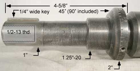
Automotive Shank
|
An automotive shank consists of a modified straight shank with whistle-notch, a Acme threaded section and
Woodruff key for locating and driving the shank within the holder. The threads are used to set the desired depth
that the automotive-shank tool holder can be inserted into the automotive adaptor by adjusting a collar (nut)
that travels along the threads.
Referred to as Auto Shank, Acme shank or Adjustable Adapter shank.
Acme threaded shanks conform to automotive standard ANSI/ASME B5.11 (1987).
|
|
 
D1
Shank
Size |
D2
Nut
Dia. |
L1
Key
Location |
Woodruff
Key Size |
L2
Nut
Width |
L3
Flat
Length |
L4
Shank
Length |
H
Flat
Depth |
1/2 - 16 |
0.88 |
0.50 |
1/8 x 5/8 |
0.38 |
1.50 |
3.00 |
0.06 |
5/8 - 16 |
1.00 |
0.50 |
5/32 x 5/8 |
0.38 |
1.50 |
3.00 |
0.06 |
3/4 - 12 |
1.25 |
0.50 |
5/32 x 5/8 |
0.38 |
1.50 |
3.00 |
0.06 |
7/8 - 12 |
1.25 |
0.63 |
3/16 x 3/4 |
0.38 |
1.88 |
3.63 |
0.06 |
1 - 12 |
1.50 |
0.63 |
3/16 x 7/8 |
0.38 |
1.88 |
3.63 |
0.06 |
1 1/16 - 12 |
1.56 |
0.63 |
3/16 x 7/8 |
0.38 |
1.88 |
3.63 |
0.06 |
1 1/4 - 12 |
1.75 |
0.69 |
? |
0.38 |
2.63 |
4.63 |
0.06 |
1 3/8 - 12 |
1.88 |
0.69 |
1/4 x 1" |
0.38 |
2.63 |
4.63 |
0.06 |
1 7/8 - 12 |
2.63 |
0.75 |
5/16 x 1-1/4 |
0.50 |
3.00 |
5.63 |
0.06 |
[Back to Top of page]
VDI Shank
 
Size |
D1 |
L1 |
D2 |
D3 |
H2 |
L2 |
L3 |
L32 |
L4 |
L5 |
R1 |
25 |
0.983
(25) |
1.9
(48.3) |
0.394
(10.0) |
2.28
(57.9) |
0.925
(23.5) |
?
(?) |
1.35
(34.3) |
?
(?) |
?
(?) |
0.28
(7.1) |
?
(?) |
30 |
1.181
(30.0) |
2.165
(55.0) |
0.551
(14.0) |
2.677
(68.0) |
1.063
(27.0) |
1.169
(29.7) |
1.575
(40.0) |
0.787
(20.0) |
0.079
(2.0) |
0.276
(7.0) |
0.984
(25.0) |
40 |
1.575
(40.0) |
2.480
(63.0) |
0.551
(14.0) |
3.268
(83.0) |
1.417
(36.0) |
1.169
(29.7) |
1.575
(40.0) |
0.787
(20.0) |
0.118
(3.0) |
0.276
(7.0) |
1.260
(32.0) |
50 |
1.969
(50.0) |
3.071
(78.0) |
0.630
(16.0) |
3.858
(98.0) |
1.772
(45.0) |
1.406
(35.7) |
1.890
(48.0) |
0.945
(24.0) |
0.118
(3.0) |
0.315
(8.0) |
1.457
(37.0) |
60 |
2.362
(60.0) |
3.701
(94.0) |
0.630
(16.0) |
4.843
(123.0) |
2.165
(55.0) |
1.720
(43.7) |
2.205
(56.0) |
1.102
(28.0) |
0.157
(4.0) |
0.394
(10.0) |
1.890
(48.0) |
[Back to Top of page]
HSK Shank (hollow taper shank system)
|
I've seen numerous references to standards for the HSK shank including:
ISO 12164, DIN 69893, DIN 29893-1 and DIN 69063-1.
The taper on all HSK shanks is 10:1.
The flange groove on forms A, B, E and F is 60 degrees
|
|
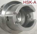
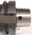
HSK-A DIN 69893-1:1996-01
For use on milling machines and milling centres with automatic tool change.
Also suitable for manual tool change.
Coolant supply through the center.


Size |
Form |
D1 |
D2 |
L1 |
L2 |
L3 |
B1 |
B2 |
B3 |
H1 |
H2 |
32 |
A |
24 |
32 |
36 |
20 |
5 |
7 |
7 |
9 |
13 |
9.5 |
40 |
A |
30 |
40 |
40 |
20 |
6 |
8 |
9 |
11 |
17 |
12 |
50 |
A |
38 |
50 |
51 |
26 |
7.5 |
10.5 |
12 |
14 |
21 |
15.5 |
63 |
A |
48 |
63 |
58 |
26 |
10 |
12.5 |
16 |
18 |
26.5 |
20 |
80 |
A |
60 |
80 |
66 |
26 |
12 |
16 |
18 |
20 |
34 |
25 |
100 |
A |
75 |
100 |
79 |
29 |
15 |
20 |
20 |
22 |
44 |
31.5 |
125 |
A |
95 |
125 |
92 |
29 |
19 |
25 |
25 |
28 |
55.5 |
39.5 |
160 |
A |
120 |
160 |
111 |
31 |
23 |
30 |
32 |
36 |
72 |
50 |
HSK-B DIN 69893-1:1996-01
Coolant supply through the flange
Enlarged flange diameter for rigidity
Drive slots are in the flange
For use on milling machines, lathes and machining centers with automatic tool change

Size |
Form |
D1 |
D2 |
L1 |
L2 |
B2 |
H1 |
H2 |
40 |
B |
24 |
40 |
36 |
20 |
10 |
16 |
? |
50 |
B |
30 |
50 |
46 |
26 |
12 |
20 |
? |
63 |
B |
38 |
63 |
51 |
26 |
16 |
25 |
? |
80 |
B |
48 |
80 |
58 |
26 |
18 |
31.5 |
? |
100 |
B |
60 |
100 |
69 |
29 |
20 |
40 |
? |
125 |
B |
75 |
125 |
79 |
29 |
25 |
50 |
? |
160 |
B |
95 |
160 |
94 |
31 |
32 |
62.5 |
? |
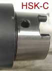
HSK-C DIN 69893-1:1996-01
Manual tool change type
For special purpose machines, transfer lines and lathes.
Coolant supply through the center.

Size |
Form |
D1 |
D2 |
L1 |
L2 |
L3 |
B1 |
32 |
C |
24 |
32 |
26 |
10 |
5 |
7 |
40 |
C |
30 |
40 |
30 |
10 |
6 |
8 |
50 |
C |
38 |
50 |
37.5 |
12.5 |
7.5 |
10.5 |
63 |
C |
48 |
63 |
44.5 |
12.5 |
10 |
12.5 |
80 |
C |
60 |
80 |
56 |
16 |
12 |
16 |
100 |
C |
75 |
100 |
66 |
16 |
15 |
20 |
HSK-D DIN 69893-1:1996-01
Manual tool change type
Coolant supply through the flange
Enlarged flange diameter for rigidity
Drive slots are in the flange
For use on milling machines, lathes, drilling and grinding machines


Size |
Form |
D1 |
D2 |
L1 |
L2 |
B2 |
H1 |
40 |
D |
24 |
40 |
36 |
20 |
10 |
16 |
50 |
D |
30 |
50 |
46 |
26 |
12 |
20 |
63 |
D |
38 |
63 |
51 |
26 |
16 |
25 |
80 |
D |
48 |
80 |
58 |
26 |
18 |
31.5 |
100 |
D |
60 |
100 |
69 |
29 |
20 |
40 |
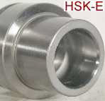
HSK-E DIN 69893-1:1996-01
High speed applications for automatic tool change.
No rear drive slots, no drive slots in the flange.
Coolant supply through the center.


Size |
Form |
D1 |
D2 |
L1 |
L2 |
25 |
E |
19 |
25 |
23 |
10 |
32 |
E |
24 |
32 |
26 |
20 |
40 |
E |
30 |
40 |
40 |
20 |
50 |
E |
38 |
50 |
51 |
26 |
63 |
E |
48 |
63 |
58 |
26 |
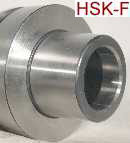
HSK-F DIN 69893-1:1996-01
High speed applications for automatic tool change.
No rear drive slots, no drive slots in the flange.
Enlarged flange diameter for rigidity


Size |
Form |
D1 |
D2 |
L1 |
L2 |
25 |
F |
? |
25 |
? |
? |
32 |
F |
? |
32 |
? |
? |
40 |
F |
? |
40 |
? |
? |
50 |
F |
30 |
50 |
46 |
26 |
63 |
F |
38 |
63 |
51 |
26 |
[Back to Top of page]
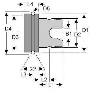
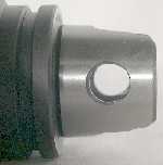
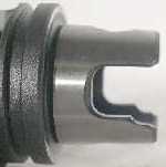
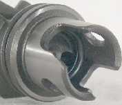
KM (VM) Shank
|
KM tooling is designed around a short 10:1 tapered shank. The taper is self centering to promote easy tool loading and unloading in both manual and
automatic applications. KM tooling is designed to have simultaneous taper and face contact. The KM clamping mechanism fits inside the taper shank of the KM unit and
utilizes two angled holes, called ball tracks, machined through the shank. The locking balls are forced radially outward by a wedge-shaped piece called the lock rod.
The Valenite VM shank is the same as the Kennametal KM shank.
|
|
Size |
D1 |
D2 |
D3 |
D4 |
D5 |
L1 |
L2 |
L3 |
L4 min. |
B1 |
KM32 |
1.260
(32.0) |
0.945
(24.0) |
1.142
(29.0) |
1.435
(36.44) |
0.138
(3.5) |
0.787
(20.0) |
0.315
(8.0) |
0.197
(5.0) |
0.394
(10.0) |
0.354
(9.0) |
KM40 |
1.575
(40.0) |
1.181
(30.0) |
1.457
(37.0) |
1.750
(44.44) |
0.138
(3.5) |
0.984
(25.0) |
0.433
(11.0) |
0.236
(6.0) |
0.472
(12.0) |
0.394
(10) |
KM50 |
1.969
(50.0) |
1.575
(40.0) |
1.681
(42.7) |
2.339
(59.40) |
0.279
(7.0) |
1.260
(32.0) |
0.472
(12.0) |
0.354
(9.0) |
0.630
(16.0) |
0.551
(14.0) |
KM63 |
2.480
(63.0) |
1.969
(50.0) |
2.193
(55.7) |
2.850
(72.40) |
0.276
(4.0) |
1.575
(40.0) |
0.709
(18.0) |
0.394
(10.0) |
0.709
(18.0) |
0.630
(16.0) |
KM80 |
3.150
(80.0) |
2.520
(64.0) |
2.862
(72.7) |
3.520
(89.40) |
0.276
(7.0) |
1.772
(45.0) |
0.728
(18.5) |
0.433
(11.0) |
0.866
(22.0) |
0.787
(20.0) |
[Back to Top of page]
Monarch Shank

Size |
Gage Dia.
D1 |
Driver Gear
D2 |
Flange
D3 |
L1 |
L2 min. |
45 |
2.250 |
2.68 |
1.75 |
2.88 |
1.00 |
[Back to Top of page]
SDH Shank (Morris Tooling)
|
Features: (from Morris Tooling literature)
Single handed, ultra fast Tool changes
High degree of repeatability.
Holder secured and released from spindle without wrenches or keys
Very high torque drive capability.
Retention unit located inside spindle to prevent damage and contamination.
Toolholder locked and released by simple 90° rotation.
An audible ("Click") confirms the holder is positively locked into the spindle.
Centralising cone ensures high concentricity.
Through Coolant facility up to 300psi.
|
|
dimensions in mm
Size |
D1* |
D2* |
L1* |
L2** |
T** |
SDH16 |
16 |
29 |
45 |
? |
? |
SDH20 |
20 |
36 |
56 |
18 |
8.8 |
SDH25 |
25 |
41 |
64 |
? |
? |
SDH28 |
28 |
44 |
64 |
19 |
9.6 |
SDH36 |
36 |
54 |
82 |
? |
? |
* dimension from Morris Tooling literature.
** measured from actual units
Morris Tooling catalog information
[Back to Top of page]
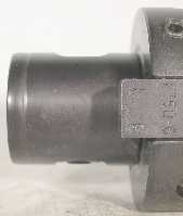
AXA Shank
|
Features:
The AXA shank (as I call it) is a 1" keyed straight shank with tapered depth adjustment collar.
The AXA Master (or chuck) has a 1" keyed straight bore with tapered recess mouth.
The shank is held in the chuck by a "draw bar" (1/2-13 cap screw) installed from the backend of the chuck shank.
All the AXA tooling I have seen were made by either "TSD Microbore, Frankenmuth, MI"
or "DeVlieg Microbore div., Royal Oak, MI" which are closely related to each other.
I have no idea if an industry standard exists for this shank or how prevalent they are.
|
|
[Back to Top of page]
Komet ABS
 
ABS Size |
d
inch (mm) |
d1
inch (mm) |
L
inch (mm) |
D2 (dia)
inch (mm) |
P (Pin)
inch (mm) |
ABS 25 |
0.984 (25) |
0.512 (13) |
0.787 (20) |
? (?) |
? (?) |
ABS 32 |
1.260 (32) |
0.630 (16) |
0.906 (23) |
? (?) |
? (?) |
ABS 40 |
1.575 (40) |
0.787 (20) |
1.102 (28) |
? (?) |
? (?) |
ABS 50 |
1.969 (50) |
1.102 (28) |
1.220 (31) |
0.51 (13) |
1/4 (6.4) |
ABS 63 |
2.480 (63) |
1.339 (34) |
1.496 (38) |
0.65 (16.5) |
3/8 (9.5) |
ABS 80 |
3.150 (80) |
1.811 (46) |
1.693 (43) |
? (?) |
? (?) |
ABS 100 |
3.937 (100) |
2.205 (56) |
2.165 (55) |
? (?) |
? (?) |
ABS 125 |
4.921 (125) |
2.756 (70) |
2.756 (70) |
? (?) |
? (?) |
ABS 160 |
6.299 (160) |
3.543 (90) |
3.543 (90) |
? (?) |
? (?) |
[Back to Top of page]
Unknown #2
|
The only information I have on this Shank is taken from units I have in hand.
I have no idea if there is an "Industry standard" that defines the shank or if its a Valenite proprietary shank.
The following dimensions are average caliper measurements, so use them accordingly.
The basic shank is the same as the Komet ABS shank, However there are 2 major differences:
The cross pin:
ABS shank has a round fixed length pin with socket on one side and point on the other
UNK#2 shank has a square pin that changes length as you turn the central socket head screw.
The indexing key:
ABS shank has small round pin, UNK#2 shank has a large rectangular tang.
|
|
 
Size |
D
inch (mm) |
D1
inch (mm) |
L
inch (mm) |
D2 (sq)
inch (mm) |
T (tang)
inch (mm) |
50 |
1.97 (50) |
1.1 (28) |
1.22 (31) |
0.47 (12) |
0.47 (12) |
[Back to Top of page]
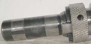
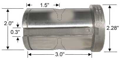
Beaver Quick Change Shank
|
The only information I have on the Beaver Quick Change Shank is taken from units I have in hand.
I have no idea if there is an "industry standard" that defines the shank or if its a Beaver Tool proprietary shank.
The following dimensions are average caliper measurements, so use them accordingly.
|
|
|
Flange thickness ranged from 0.35" to 0.5"
on the 5 units I measured.
Key-slot depth is approximately 0.2".
The dimples are approximately 0.4" deep,
3/8" dia throat and 0.6" dia. mouth.
|
 
[Back to Top of page]
Unknown Taper #1
|
I don't know who made it, developed it or if there is an industry standard.
The following dimensions are taken from 2 Endmill Holders I have.
If you know what these are, Please enlighten the rest of us.
Gerry S. in Australia says the taper is the same as the taper on the tooling for his "herbert no1 horizontal and
vertical milling machine", however the drive system is different. His holders have a driving ring with two
cutouts at 180 deg. to each other which engage lugs on the spindle, while these have lugs which engage
cutouts on the spindle.
|
|
 
Measured values from actual units.
D1 |
D2 |
D3 |
L1 |
L2 |
L3 |
L4 |
L5 |
0.73 |
1.405 |
1.415 |
2.35 |
2.72 |
0.32 |
0.55 |
2.21 |
[Back to Top of page]
Weldon Shank
|
Standard Weldon Shank produced by The Weldon Tool Company.
Lots of other manufactures produce shanks with a "Weldon Flat".
|
|
 
S |
U |
V |
W min. |
W max. |
X |
Y |
3/8 |
1-9/16 |
25/32 |
0.280 |
0.282 |
0.050 |
~ |
1/2 |
1-25/32 |
57/64 |
0.330 |
0.332 |
0.060 |
~ |
5/8 |
1-29/32 |
61/64 |
0.400 |
0.402 |
0.065 |
~ |
3/4 |
2-1/32 |
1-1/64 |
0.455 |
0.457 |
0.065 |
~ |
7/8 |
2-1/32 |
1-1/64 |
0.455 |
0.457 |
0.065 |
1/2 |
1 |
2-9/32 |
1-9/64 |
0.515 |
0.517 |
0.075 |
1/2 |
1-1/4 |
2-9/32 |
1-9/64 |
0.515 |
0.517 |
0.094 |
1/2 |
1-1/2 |
2-11/16 |
1-3/16 |
0.515 |
0.517 |
0.094 |
9/16 |
2 |
3-1/4 |
1-27/32 |
0.700 |
0.702 |
0.100 |
27/32 |
2-1/2 |
3-1/2 |
1-15/16 |
0.700 |
0.702 |
0.100 |
27/32 |
Tolerances
Element |
Range |
Direction |
Tolerance |
S |
All Sizes |
Minus |
0.0001 to 0.0005 |
U |
All Sizes |
Plus or Minus |
1/32 |
V |
All Sizes |
Plus or Minus |
1/64 |
X |
All Sizes |
Minus |
1/64 |
Y |
7/8" to 2-1/2" |
Plus or Minus |
1/32 |
[Back to Top of page]
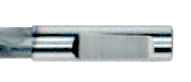
Whistle Notch Shank - DIN6535 form HE
|
The following are sample Whistle Notch shanks that purport to comply with DIN6535 form HE
|
|

[Back to Top of page]
Note:
The specifications and information provided on this page are intended for part identification purposes only.
Although we believe them to be correct, dimensions should not be used for part construction or inspection.
The above information was collected from numerous sources, including:
Kennametal "Machining Center Tooling" Catalog.
Briney Tooling Systems
TSD Tooling Systems Division
Milling Machine Tapers by Rick Dulas
Logan Actuator Website
Practical Machinist Forum Discussions
|
|

 Inventory Index
 Inventory Index