|
|
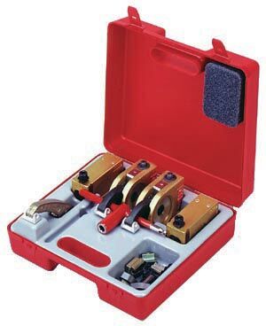
KOPAL Mono-Bloc Clamp suit-case set # 06-100
|
|
Set contains:
- 2 ea. Mono-Bloc with long clamping arm 06-030
- 2 ea. Elevator underbody 06-050
- 1 ea. Extension arm (90mm) 05-140
- 3 ea. #1 Standard shoes 05-565
- 1 ea. T-Wrench 06-160
- 4 ea. Cap Scews (M10) with square washers
- 6 ea. M10 T-Slot Nuts with leaf spring
(2ea. 14, 16 & 18mm)
|
| |
|
|
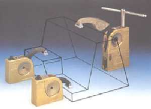
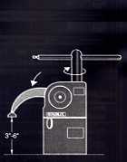
The Mono-Bloc clamp is the quickest and easiest way to clamp parts on a mill!
|
|
- One of the fastest and strongest milling clamps available anywhere.
- Modular design: Start with two clamps and build up with risers.
- Clamps are easily set up and broken down, making
them ideal for odd-shaped parts and short cycle times.
- Worm-and-gear design ensures that the clamp will not loosen with use.
- Up to 12" clamping height with riser blocks.
|
|
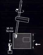
How The Mono-Bloc Clamps Work
|
|
|

|
|
|
1. Slide T-Nut and screw into approximate position. Slide riser block (or Mono-Bloc) over M-10 screw.
Tighten M-10 screw through opening in riser block with T-wrench.
|
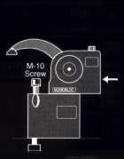
2. Slide Standard-Duty Mono-Bloc over M-10 screw on riser block.
|
3. Tighten M-10 screw on riser block with T-wrench through clearance on Mono-Bloc.
|
4. Clamp the part. Range is 3" to 6". Add up to three riser blocks to clamp parts up to 12" high.
|
|
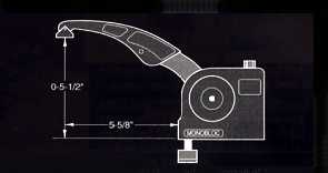
Long Arm
|
with Extension Arm
|
|
|
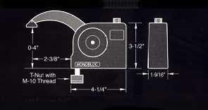
- Clamping Range 0-4"
- 2,400 lbs. clamping force when tightened to a torque of 58 ft. lbs.
|
- Clamping Range 0-5 1/2"
- 1,300 lbs. clamping force when tightened to a torque of 58 ft. lbs.
|
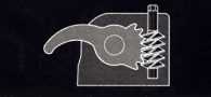
Precision Worm
& Gear Mechanism
|
#1 Swivel Shoe
|
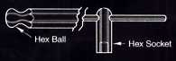
T-Wrench
|
|

|
|
When holding the workpiece, the worm can turn the gear but the gear cannot turn the worm.
Thus, the clamp cannot loosen.
|
Light alloy swivel shoe provides protection against marring workpiece. It is removable and free to
swivel. It is secured by spring-loaded balls and a variety of shoes are available.
|
8mm hex bal is used to tightened Mono-Bloc to riser or to table; socket is used to clamp workpiece.
|
Note:
The specifications and information provided on this page are intended for part identification purposes only.
Although we believe them to be correct, dimensions should not be used for part construction or inspection.
|
|

 Inventory Index
 Inventory Index